





Introduction
Multifunctional Magneto-optical Kerr Microscopic Imaging System is an advanced scientific research equipment with high sensitivity, high resolution and multiple functions. The system realizes non-contact, real-time dynamic imaging of magnetic properties of materials through the magneto-optical Kerr effect, and can clearly and intuitively understand the spatial distribution and time evolution of magnetization states in magnetic materials and devices, which is suitable for the testing and product development of magnetic materials and spintronic devices.
The magneto-optical Kerr micro-imaging system is based on the self-designed optical path structure, and adopts photoelectric components of Olympus and Soleibo. It is used for magnetic domain imaging and dynamics studies of magnetic materials/spintronic devices.
Technical characteristics
High sensitivity: The system adopts advanced magneto-optical detection technology, which can detect weak magneto-optical signals and realize fine observation of material magnetic domain structure.
High resolution: The system is equipped with a high-precision microscope and imaging system, which can present a clear image of the microscopic magnetic domain, providing intuitive evidence for the study of the magnetic properties of materials.
Versatility: In addition to the basic magnetic domain imaging function, the system also has magnetic field control, temperature control, spectral analysis and other extended functions to meet diverse scientific research needs.
Easy to operate: the system adopts humanized design, the interface is simple and clear, easy to operate, and is equipped with intelligent data analysis software, which can automatically process experimental data and improve efficiency.
Multifunctional Probe Station
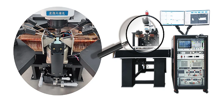
With in-plane magnetic field, vertical magnetic field, and multiple pairs of DC/HF probes - the perfect combination of magneto-optical imaging and spin transport testing!
The maximum vertical magnetic field 1.8 T, 1.4 T in-plane magnetic field, 4K-873K variable temperature, can be used for imaging research of hard magnetic materials
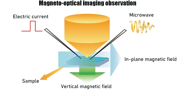
Principle diagram
Multifunctional control system
Test signal control
1. Vertical magnetic field/in-plane magnetic field/current/microwave and other multiple signals, applied synchronously at μs level;
2. The waveform, amplitude, frequency, relative delay and other parameters of each signal can be easily adjusted.
Image processing
- Real-time subtraction to eliminate background noise;
- Automatic correction of vibration drift, etc.
Signal analysis
1. Real-time display of current and magnetic field test signals;
2. Based on Kerr image analysis, perform hysteresis loop scanning on the sample locally (220 nm) or globally.
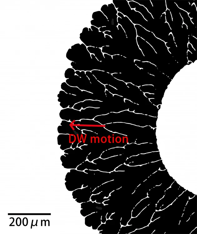
Magnetic Domain Imaging Effects in Perpendicularly Anisotropic Magnetic Films (1 nm Thick)
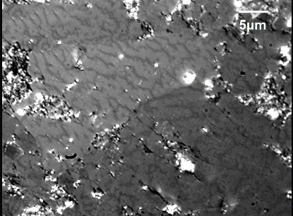
Magnetic domains on the surface of permanent magnet (NdFeB) bulk
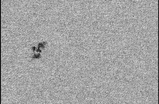
Nanofilm material

Magnetic domains on the surface of silicon steel block
Typical application
Study the properties of magnetic materials
(1)Detect the quality of magnetic materials
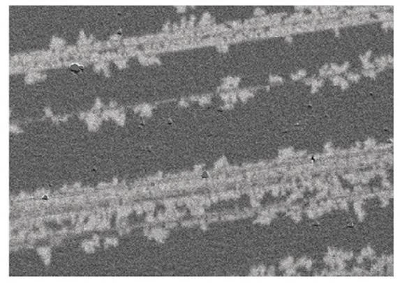
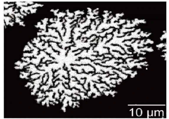
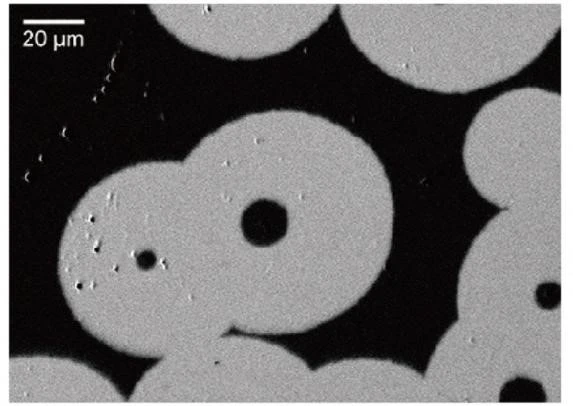
|
MgO(sub)/Co/Pt sample: |
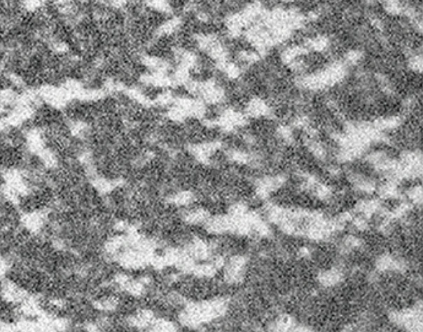
Poor quality magnetic film, snowflake-like magnetic domains appear during the magnetic reversal process. |
High-quality magnetic film with uniform magnetic domain structure and smooth edges. |
(2)Detect defect location
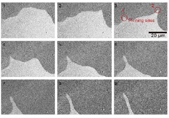
At the defect, the magnetic domain wall moves and deforms, forming a pinning effect. Using a high-resolution objective lens, the defect position can be directly observed (red circle)
(3)Damage detection of spintronic devices
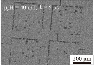
During the microfabrication process of spintronic devices, the edge of the sample is damaged, which leads to a decrease in stability under the action of a magnetic field, and the edge is first flipped.
(4)Analyzing the hysteresis loop results
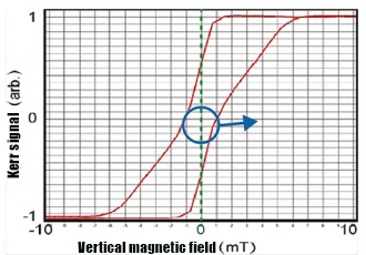
Magneto-optical Kerr microscope can analyze the magnetic domain state corresponding to the hysteresis loop due to its spatial resolution advantage. As shown on the left, the sample exhibits spontaneous demagnetization due to the dominance of dipole effects over anisotropy.
The unique characterization capabilities of Kerr microscopes:
The Kerr microscope has a comprehensive set of methods to characterize almost all magnetic eigenparameters.
Compared with other characterization methods, its significant advantage is that it can perform fine characterization of local nature in a very small area (220 nm). This kind of microscope is very suitable for all kinds of magnetometry experiments, such as irradiation, voltage control and opto-magnetic control, and can effectively analyze materials with non-uniform properties.
Characterization of the local saturation magnetization properties M: By observing the distance change of the magnetic domain wall under different magnetic fields, the Kerr microscope can extract the local saturation magnetization M. The principle of this method is based on the phenomenon of mutual repulsion caused by the dipole interaction when the magnetic domain walls are close to each other. The method was first proposed and validated in 2014 by Professor Nicolas Vernier of the University of Paris Saceray, and is highly consistent with VSM measurements.
Characterization of local anisotropic energy k: By analyzing the light and dark changes of local Kerr images, the hysteresis loop can be obtained, and then the equivalent anisotropic field strength of the local region can be extracted.
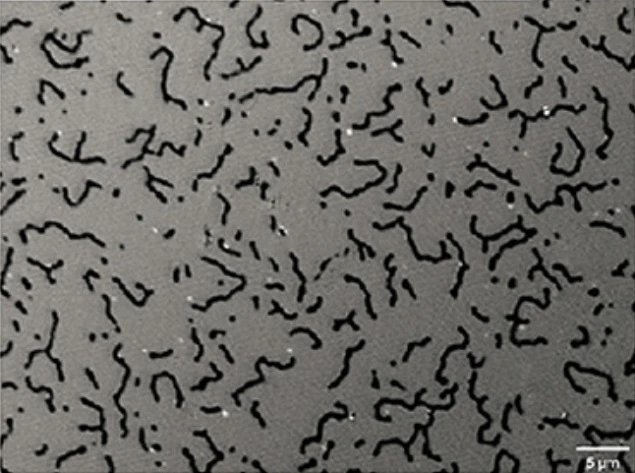
Measurement of the Heisenberg exchange interaction constant: Using the Kerr microscope's magnetic field "custom waveform" function, we can oscillate demagnetization of the sample. Then, the Fourier transform of the obtained labyrinth domain map can accurately determine the domain width, and then extract the Heisenberg exchange interaction stiffness.
Characterization of Dzyaloshinskii-Moriya interaction (DMI) : By observing the asymmetric expansion of the magnetic domain wall under the combined action of the in-plane magnetic field and the vertical magnetic field, the Kerr microscope can measure the DMI intensity of the thin film material.
Magnetic Domain Wall Dynamics Study
Method: First, a magnetic field or current pulse with amplitude B and width t is applied. Then, the Kerr images before and after the pulse were obtained, and the distance d of the domain wall movement was obtained by difference calculation. Finally, the velocity of the domain wall is calculated according to the velocity formula v=d/t.
Note: The measurement of ultrafast domain wall motion requires the use of ultra-short signal pulses in a limited field of view. The system is configured with a magnetic field with a response speed of μs, enabling the measurement of domain wall velocities up to 200 m/s.
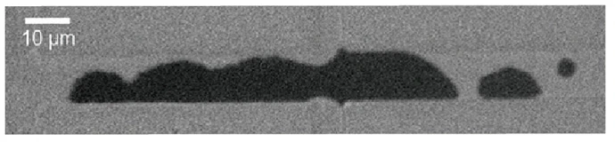
Observation of the effect of magnetic domain wall tension: Using ultrafast magnetic field pulses in the order of microseconds, we can generate magnetic bubbles in tiny samples. For the first time, we have successfully observed the spontaneous contraction of magnetic domain walls under their own tension by means of a high-resolution Kerr microscope.
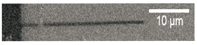
The phenomenon of domain walls pinned on Hall rods: Using magnetic field pulses, we can precisely control the position of the domain walls in the nanowire. By observing the pinning process of the magnetic domain wall, we can measure the data related to the pinning magnetic field.
Spin transport property test + imaging
1. Magnetic domain wall motion driven by STT current.
Through the equipped probe and the arbitrary waveform generator of the main control system, a square wave of 50 ns~s level can be applied to the sample, and the magnetic domain wall motion can be observed and the velocity can be measured.
2. Magnetic domain wall motion under the joint action of STT current and vertical magnetic field.
In some materials, purely current-driven domain wall motion cannot be observed. At this time, the ultrafast magnetic field pulse at the μs level of this device can be synchronized with the current to observe the domain wall motion driven by the vertical magnetic field + current, so as to analyze various physical effects, such as the spin polarizability of the heavy metal/ferromagnetic system due to The effect of spin scattering reduction.
3. Magnetic domain wall motion under the joint action of current and in-plane magnetic field.
The Hall spin current interacts with the in-plane magnetic field to induce a magnetic moment flip, the so-called SOT flip. The in-plane magnetic field and electrical test system configured by this equipment can not only realize the electrical test of this process, but also use the synchronization function of the camera and the signal acquisition card to analyze the magnetic domain state corresponding to the flip curve point by point.
4. Introduction to transport testing.
With Keithley 6221 and 2182A source meter, it can measure Hall effect, I-V characteristic (resistivity) and magnetoresistance (MR). With microwave source, microwave probe and lock-in amplifier, etc., ST-FMR and second harmonic test can be performed to characterize the spin-orbit moment of the sample.
Imaging effect
1.220 nm (100x oil immersion objective) / 450 nm (long working distance objective, tip compatible);
2. Maximum field of view: 1.2 mm×1 mm (5x objective lens);
3. It can detect the magnetic change of 2 atomic layer thin films.
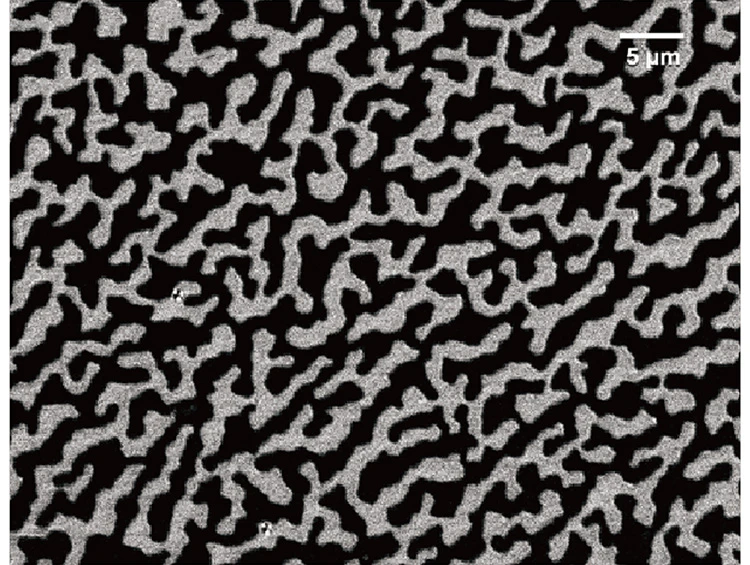
CoFeB(1.3nm)/W(0.2)/CoFeB(0.5) Labyrinth domains in thin films
Image Processing
With any image as the background, real-time subtraction noise image drift correction, automatic addition of scale and other functions.
Deliver, shipping and serving
We offer diverse shipping options including sea, air, and express delivery, tailored to meet the unique needs of our customers. Our priority is to provide cost-effective and prompt delivery services that meet their expectations.



FAQ