


Input Channel
With the low-noise analog pre-amplifier, the signal input of DXA-001 can be switched to operate in the single-ended or differential voltage mode, and the input noise is 10 nV/√Hz. The input impedance is 10 MΩ and the full-scale input voltage sensitivity ranges from 1 nV to 1V. Besides, DXA-001 can also be used for current measurements with variable current gains of 10^6 or 10^8 V/A. Two line filters (50/60 Hz and 100/120 Hz) are designed to eliminate line related interference. The programmable gain amplifier is provided to adjust the dynamic reserve of the system according to the magnitude of the input signal, so that DXA-001 has an inherently large dynamic reserve up to 100dB. The sampling rate of 312.5KSPS is determined by a precision 24-bit A/D converter and a specific filter is designed to avoid aliasing.
Reference Channel
In order to provide the reference signal for DXA-001, an externally applied sine wave or square wave, or its own internally synthesized reference source could be used. When the instrument is set to internal reference mode, the internal precision stabilized oscillator and the digital synthesized algorithm are used to generate sinewave output that multiplies the input signal, there is virtually no reference phase noise when choosing internal reference mode. Taking advantage of the digital phase-shifting technique, the reference signal phase could be adjusted with 0.01° resolution. The internal reference mode can operate at a fixed frequency from 1 MHz to 100 kHz. In addition, the external reference is also applicable to DXA-001, including the sinewave reference signal and TTL logic reference signal. The rising and trailing edge of the external reference signal are applied to trigger off the internal Phase Locking Loop (PLL). Based on the frequency of the reference signal, harmonic detection can be performed by DXA-001. The maximum frequency of the measurable harmonics is 32767 times of basic frequency, and it is also less than the maximum operational frequency of 100 kHz.
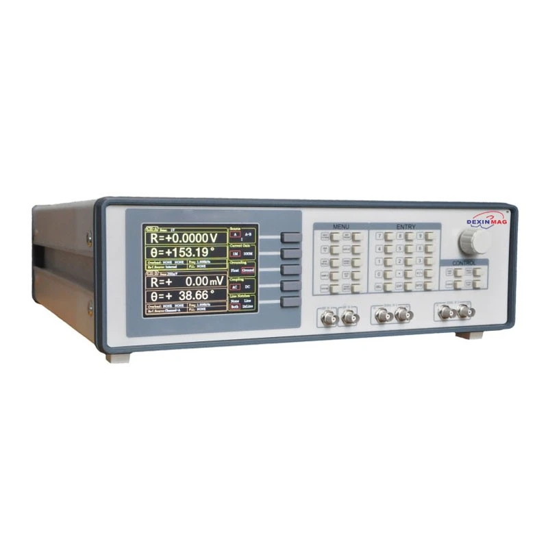
Display
DXA-001 uses the 5.6 inch 640×480 TFT color display as its screen. Data measured by DXA-001, such as, X, Y, R, θ, is stored in up to four traces. Trace values can be displayed as a bar graph or as a strip chart showing the trace values as a function of time.

Besides, DXA-001 can display polar plots, showing phasor composed of in-phase and quadrature components of the signal. All displays can be easily scaled by manual operation, and the auto-scale feature is available to optimize display quickly. The screen can be configured as a single large display or two horizontally-split displays.


Simultaneous Multiple-harmonic Measurement
The traditional phase-locked amplifier can only measure fundamental frequency signal or one certain harmonic ware at the same time, so it can not meet the requirement in some occasions when measuring multiple frequency components simultaneously is needed. On the digital end, DXA-001 combined FPGA and ARM technology, which has wider processing bandwidth and a more flexible digital framework. The digital processing precision could reach 48 bits and could measure 3-channel harmonic components simultaneously, which makes one DXA-001 is equal to three traditional phase-locked amplifiers.
Remote Operation
The built-in RS232 to USB interfaces on DXA-001 allow full manual operation from a controlling computer, including setting or interrogating control and reading out data. Free LabVIEW program is provided. It makes it easy to set up and run complex experiments, such as remote control of every instrument function. The display menu offered by the LabVIEW program allows customers to observe all commands received and responses generated by the instrument.
Signal Channel
| Voltage input Mode | Single-ended or Differential |
| Full-scale Sensitivity | 1 nV to 1 V in a 1-2-5 sequence |
| 1 fA to 1 µA | |
| Current input | 106 or 108 V/A |
| Impedance | |
| Voltage | 10 MΩ |
| Current | 1 kΩ to virtual ground |
| C.M.R.R | >100 dB to 10 kHz, decreasing |
| Dynamic reserve | >120 dB |
| Gain accuracy | 0.2% typ, 1% max |
| Voltage Noise | 5 nV/√Hz at 997 Hz |
| Current Noise | 5 fA/√Hz at 97 Hz |
| 13 fA/√Hz at 997 Hz | |
| Line filters | 50/60 Hz and 100/120 Hz |
| Grounding | BNC shield can be grounded or floated via 10 kΩ to ground |
Reference Channel
| Input | |
| Frequency range | 1 mHz to 102 kHz |
| Reference input | TTL or Sine |
| Input impedance | 1 MΩ |
| Square reference level | VIH>3V, VIL<0.5V |
| Sine reference signal | >1 Hz |
| > 400 mVpp | |
| Phase | |
| Resolution | 0.001° |
| Absolute phase error | <1° |
| Relative phase error | <1 mdeg |
| Phase noise | |
| Internal ref. Synthesized, <0.0001 deg at1 kHz | |
| External ref. 0.001 deg at 1 kHz (100 ms time constant, 12 dB/oct) | |
| Drift | |
| <0.01 deg/℃ below 10 kHz | |
| <0.1 deg/℃ above 10 kHz | |
| Harmonic detection | 2F, 3F, …nF to 102 kHz (n<32,767) |
| Acquisition time | |
| Internal Ref. | Instantaneous acquisition |
| External Ref. | (2 cycles + 5 ms) or 40 ms, whichever is larger |
Demodulator
| Stability | |
| Digital outputs | no zero drift on all sets |
| Display | no zero drift on all sets |
| Analog outputs | <5 ppm/℃ for all dynamic reserve settings |
| Harmonic rejection | -90 dB |
| Time constants | 10 µs to 3 ks (<200 Hz) |
| 10 µs to 30 s (>200 Hz) | |
| Synchronous filters | Available below 200 Hz(18, 24 dB/oct rolloff) |
Internal Oscillator
| Frequency | Range 1 mHz to 102 kHz |
| Accuracy | 2 ppm + 10 µHz |
| Resolution | 1 mHz |
| Distortion | -80 dBc (f<10 kHz),-70 dBc (f>10 kHz) |
| Amplitude | 0.001Vrms to 5 Vrms ( Resolution:1 mVrms) |
| Accuracy | 1% |
| Stability | 50 ppm/℃ |
| Sine Outputs | |
| Sine signal, output impedance 50 Ω | |
| TTL Outputs | 5V TTL/CMOS level, output impedance 200Ω |
Display
| Screen | 5.6 inch, 640×480 TFT |
| Screen Format | Single or dual display |
| Display quantities | Each display shows one trace, |
| traces can be defined as X, Y, R, θ | |
| Display types | Numerical form, bar graph, polar plot and strip chart |
AUX Inputs and Outputs
| CH1 and CH2 Outputs | |
| Function | Output X, Y, R, θ |
| Output Voltage | ±10 V full scale. |
| 30 mA max output current | |
| Update Rate | 312.5kHz |
| AUX Inputs | |
| Function | 4 Channel Inputs |
| Amplitude | ±10 V,1 mV resolution ratio |
| Impedance | 1 MΩ |
| AUX Outputs | |
| Function | 4 Channel Outputs |
| Amplitude | ±10 V,1 mV resolution ratio |
| Drive current | ±25mA max |
| Trigger Input | |
| Function | TTL external trigger is used for data storage |
| Monitor Output | |
| Function | Analog output of a signal-amplifier |
| Drive current | ±40mA max |
Interfaces
RS-232 to USB interface,
IEEE-488 interface(optional).
General
| Power requirements | |
| Voltage | 220~240 V AC |
| 100~120 VAC(optional) | |
| Frequency | 50/60 Hz |
| Power | 30 W |
| Power supply rejection | 70dB@1MHz |
| Weight | 11 KG |
| Dimensions | |
| Width | 448 mm |
| Depth | 513 mm |
| Height | |
| With feet | 148 mm |
Deliver, shipping and serving
We support shipping by sea, air, and express delivery. Our services cater to a range of shipping needs, ensuring that our customers can choose the best option for their specific requirements. We aim to meet their expectations by providing cost-effective and timely deliveries.
In addition to our shipping capabilities, we also prioritize quality customer service. Our team is always ready to provide timely and relevant information about your shipment, making sure to keep you informed every step of the way.


FAQ
1. What is a lock-in amplifier?
Answer: A lock-in amplifier is a precision electronic instrument used to measure and amplify specific frequency components in a signal. By phase-locking with the input signal, it can accurately extract weak signals buried in noise background. Lock-in amplifiers are commonly used in experimental research and precise measurements in fields such as optics, electronics, and magnetism.
2. How does a lock-in amplifier work?
Answer: The basic principle of a lock-in amplifier is to phase-synchronously lock the signal to be measured with a reference signal, and after filtering, amplification, etc., it outputs a signal in which both amplitude and phase information have been measured. This method effectively extracts weak signals, suppresses background noise, and improves measurement sensitivity and accuracy.
3. What are the application areas of lock-in amplifiers?
Answer: Lock-in amplifiers are widely used in scientific research, industrial production, and precision instrumentation fields. In optical experiments, lock-in amplifiers are used to measure optical interference, optical scattering, and other phenomena; in the electronics field, they are used to detect weak signals and noise interference; in the biomedical field, they are used for control and monitoring of treatment devices, and so on. In general, lock-in amplifiers play an important role in improving signal measurement accuracy and noise suppression.