


Input Channel
DXA-002 detects an input signal in a single-ended mode or a differential voltage mode. With an ultra low-noise pre-amplifier, the input noise is as low as 9 nV/√Hz@997 Hz. The input impedance is 10 MΩ and the full-scale input voltage sensitivity ranges from 1 nV to 1 V. Besides, DXA-002 can be used for current measurement with gains of 10^6 or 10^8 V/A. Two line filters (50/60 Hz and 100/120 Hz) are designed to eliminate power frequency interference. A programmable gain amplifier is used to adjust the dynamic reserve of the system, so that DXA-002 can keep a high dynamic reserve of 120 dB.
Reference Channel
The reference signal can work in external mode or internal mode. In internal mode, a precise and stable internal oscillator generates a sine wave as an internal reference that is multiplied by the input signal. This internal signal is without any phase noise. With the digital phase-shifting technique, the phase resolution of the reference signal is 0.01 deg. DXA-002 can work at any fixed frequency from 50 mHz to 120 kHz in this mode. In external mode, the reference signal can be a sine wave or a TTL pulse or a square wave. The rising or falling edge of the external reference signal triggers the Phase Lock Loop (PLL) to lock the external signal. Based on the frequency of the reference signal, the DXA-002 can detect the harmonics of the input signal. The maximum harmonic signal frequency can reach 32,767 times the fundamental frequency, and the maximum harmonic frequency cannot exceed the maximum operating frequency of the instrument by 120 kHz.
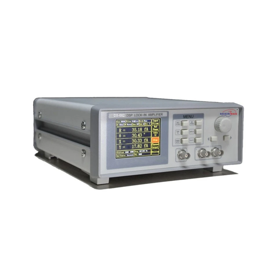
Display
DXA-002 has a 3.5-inch 320 x 240 color TFT-LCD. The measurement results of DXA-002, such as X, Y, R, and θ, are shown in numerical form.

Internal Oscillator
The internal oscillator of DXA-002 generates a low distortion (–80 dBc) sine reference signal varying from 50 mHz to 120 kHz, which has a high frequency resolution of 1 mHz. The frequency and amplitude of the reference signal can be set by using the front panel of DXA-002 or the communication interface. When DXA-002 is set in the external reference mode, the internal reference signal is phase-locked with the external reference signal.

Signal Generator
DXA-002 uses a high precision digital-to-analog converter (DAC) to output a sine wave signal at the same frequency as the internal reference signal. The amplitude and phase of the output sine wave can be set through the DXA-002's display, where the maximum amplitude of the sine wave is 1 Vrms.
Manual Operation
All functions of DXA-002 can be selected through the knobs and left and right keys on the interface, and the parameters of the response can be set directly through the Settings button in the right bar. This instrument is equipped with the corresponding free LabVIEW program, which can effectively use all the test functions of DXA-002, including setting the reasonable control parameters of the instrument and reading and saving the measured data of the instrument. This makes DXA-002 easy to use in complex scientific experiments. On the LabVIEW interface, users can see all control commands and instrument feedback responses.
Signal Channel
| Voltage input Mode | Single-ended or Differential |
| Full-scale Sensitivity | 1 nV to 1 V in a 1-2-5 sequence |
| Current input | 106 or 108 V/A |
| Impedance | |
| Voltage | 10 MΩ//25 pF,Ac or DC coupling |
| Current | 1 kΩ to virtual ground |
| C.M.R.R | >100 dB (within 100kHz), >90dB (beyond 100kHz) |
| Dynamic reserve | >100 dB |
| Gain accuracy | 0.2% typ, 1% max |
| Voltage Noise | |
| 997Hz | 9 nV/√Hz |
| Current Noise | |
| 97 Hz | 0.13 pA/√ Hz |
| 997Hz | 0.14 pA/√ Hz |
| Line filters | 50/60 Hz and 100/120 Hz |
| Grounding | BNC (A/I, B)shield can be grounded or floated via 10 kΩ to ground |
| Stability | 2ppm/℃ |
Reference Channel
| Input | |
| Frequency range | 50 mHz to 120 kHz |
| Reference input | TTL or Sine |
| Input impedance | 1 MΩ//25pF |
| Phase | |
| Resolution | 0.01° |
| Absolute phase error | <1° |
| Relative phase error | <0.01° |
| Phase noise | |
| Internal ref. | Synthesized, <0.0005°rms at1 kHz |
| External ref. | 0.01°rms at 1 kHz (100 ms time constant, 12 dB/oct) |
| Drift | |
| Below 10 kHz | <0.01°/℃ |
| Above 10 kHz | <0.1°/℃ |
| Acquisition time | |
| Internal Ref. | Instantaneous acquisition |
| External Ref. | (10 cycles + 40 ms) or 100 ms |
Display
| Screen | 3.5 inch, 640×480 TFT Color LCD |
| Screen format | Single or dual display |
| Display quantities | Each display shows one trace, |
| traces can be defined as X,Y,R,θ | |
| Display types | Numerical form, bar graph, XY plot and polar plot |
| Color style | yellow, green |
| AUX Inputs and Outputs | |
| CH1 and CH2 Outputs | |
| Function | Output X, Y, R, θ and harmonic |
| Voltage | ±10 V |
| Drive current | ±30mA max |
Interfaces
| RS-232 to USB | RS-232 to USB2.0 interface |
| RS-232 interface | Standard 9-pin RS-232 male socket |
| IEEE-488 interface(optional) |
General
| Power requirements | |
| Voltage | 220~240 V AC |
| Frequency | 50/60 Hz |
| Power | Standard 10W, Max. 20W |
| Power supply rejection | 70dB@1MHz |
| Weight | 3.2 KG |
| Dimensions | |
| Width | 259 mm |
| Depth | 320 mm |
| Height | |
| With feet | 115 mm |
| Without feet | 102 mm |
Deliver, shipping and serving
We support shipping by sea, air, and express delivery. Our services cater to a range of shipping needs, ensuring that our customers can choose the best option for their specific requirements. We aim to meet their expectations by providing cost-effective and timely deliveries.
In addition to our shipping capabilities, we also prioritize quality customer service. Our team is always ready to provide timely and relevant information about your shipment, making sure to keep you informed every step of the way.


FAQ
1. What is a lock-in amplifier?
Answer: A lock-in amplifier is a precision electronic instrument used to measure and amplify specific frequency components in a signal. By phase-locking with the input signal, it can accurately extract weak signals buried in noise background. Lock-in amplifiers are commonly used in experimental research and precise measurements in fields such as optics, electronics, and magnetism.
2. How does a lock-in amplifier work?
Answer: The basic principle of a lock-in amplifier is to phase-synchronously lock the signal to be measured with a reference signal, and after filtering, amplification, etc., it outputs a signal in which both amplitude and phase information have been measured. This method effectively extracts weak signals, suppresses background noise, and improves measurement sensitivity and accuracy.
3. What are the application areas of lock-in amplifiers?
Answer: Lock-in amplifiers are widely used in scientific research, industrial production, and precision instrumentation fields. In optical experiments, lock-in amplifiers are used to measure optical interference, optical scattering, and other phenomena; in the electronics field, they are used to detect weak signals and noise interference; in the biomedical field, they are used for control and monitoring of treatment devices, and so on. In general, lock-in amplifiers play an important role in improving signal measurement accuracy and noise suppression.